
I. Purpose & Scope
To safely and effectively provide instruction on the inspection and proper use of walk behind saw.
II. Definitions
Standard PPE – High Viz Garment, Hard Hat, Z-87.1 Safety Glasses, Gloves, Pants, Work Boots
III. Process
NOTE: Work instruction does not supplement the manual. For specific instructions for the exact model please refer to the owner’s manual.
A. Potential Hazards
- Fire
- Explosion
- Inhalation of fumes
- Burn hazard
- Carbon Monoxide Exhaust Emissions
- High noise hazard
- Sharp Objects
- Flying Debris
B. PPE
- Standard PPE
- Hearing Protection
- Respiratory Protection – recommended
C. Inspection
- Inspect the blade, flanges and shafts for damage before use.
- Front Pointer must be checked for alignment with blade.
- Lay a straight edge along Inner Flange.
- Align Front Pointer to straight edge.
- If required, adjust Front Pointer by loosening nuts that hold Guide Wheel in place.
- Align Guide Wheel to straight edge and re-tighten nuts.
- Check that water tubing in the Blade Guard is open and that each side of blade has an adequate supply of water.
- Test the water supply for pressure and quantity (flow) before starting the saw.
- Check engine oil level.
- Check blade guard for damage.
- Check engine air filter, replace if dirty.
- Clean machine daily.
D. Use
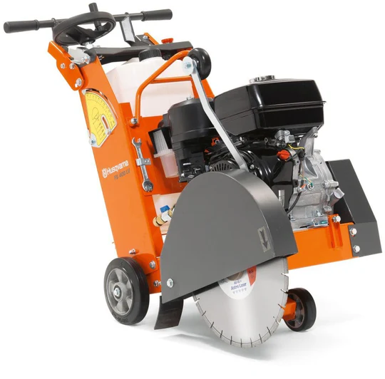
Transporting & Lifting Machine:
- Lift machine only from Lifting Point.
- Always remove blade before lifting, loading or transporting.
- Use a proper lifting strap rated for at least the maximum mass of the machine. The nominal and maximum mass of the machine are shown in the Technical Data section of the owner’s manual.
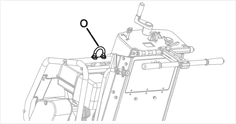
Lifting Machine Equipped with Water Tank:
- Empty water from tank.
- Remove blade.
- Lower machine until frame is parallel to ground.
- Pivot front of water tank upward until it rests against aluminum cowl top. Do not rest water tank cap against plastic cowl front – damage during lifting could occur.
- Attach proper lifting strap to Lifting Point.
- Test lift machine at a low level (just a few centimeters) to verify tank remains secured to machine, and will not be damaged or cause damage.
- If water tank equipped machine cannot be lifted without damage to the machine or tank, remove water tank before lifting.
Parking Machine:
- Pull lever toward center of machine.
- Rotate level upward 180 degrees.
- A spring allows lever to move toward outside of machine, to engage against wheel hub.
- To disengage, pull the lever toward center of machine.
- Rotate lever downward 180 degrees and release to lock in position.
Fitting the Diamond Blade
- Install Diamond Blade at job site. Do not transport the machine with the Diamond Blade installed.
- Open the Front Cover.
- Set Engine Start Switch to OFF position.
- Raise Diamond Blade to the highest position by turning Blade Depth Control Counter-Clockwise.
- Use 13mm Wrench located in Tool Compartment, to loosen and remove four M8 bolts that attach Blade Guard Latch Plate. Temporarily remove Blade Guard Latch Plate.
- Raise Blade Guard Front.
- Using the 27mm Blade Shaft Wrench, loosen and remove the Blade Shaft Nut that secures the Outer Flange in position.
- Remove Outer Flange.
- Check that Blade Shaft Arbor, Inner Flange, and Outer Flange are clean and free of foreign objects.
- Fit Diamond Blade onto Blade Shaft Arbor.
- Install Outer Flange onto Blade Shaft Arbor. Make sure that Locking Pin passes through Diamond Blade and into Inner Flange.
- Rotate Outer Flange and Diamond Blade in opposite direction of blade rotation to remove backlash.
- Install Blade Shaft Nut. Tighten using 27mm Blade Shaft Wrench.
- Lower Blade Guard Front.
- Re-install and tighten Blade Guard Latch Plate.
Starting and Cutting with Machine
- Using the Depth Control, raise Diamond Blade as high as possible so it will not strike pavement when maneuvering. Pull out on Blade Depth Stop if required.
- Dis-engage parking brake (if equipped)
- Maneuver machine into position near line to be cut.
- Lower Front Pointer onto cutting surface.
- Set Depth Indicator (use if desired)
- Lower machine until diamond blade contacts cutting surface.
- Set Depth Indicator dial to align indicator arrows with zero. Orange color indicates cutting depth in centimeters. White color indicates inches.
- Raise saw to maximum height. Now as Diamond Blade is lowered, Depth Indicator will show cutting depth.
- Return Diamond Blade to fully raised position.
- Verify that both Emergency Stop Switch and Engine Start Switch are in “ON” position. Emergency Stop Switch should be in outer position (pulled outward from cowl). Engine Start Switch must be turned to “1” (ON) position.
- Start Engine.
- Visually Verify that tool rotation matches directional arrow on blade guard.
- Open Water Control Valve FULL open. Verify full water flow, and ten adjust for proper amount of water on the blade BEFORE you lower the Blade.
- Make final adjustments to align saw with cutting line. Verify that Guide Wheel, and Diamond Blade are both on the cutting line.
- If water supply is interrupted, stop cutting immediately. Damage to Diamond Blade could occur.
- Lower Diamond Blade into the cut by slowly turning Blade Depth Control COUNTER-CLOCKWISE.
- When desired depth of cut is reached, push Blade Depth Stop down to lock it to Blade Depth Control (if desired).
- Gently push Rear Handle to propel machine forward. Watch Diamond Blade and Guide Wheel carefully to assure that machine stays on cutting line.
- When cut is complete, dis-engage Blade Depth Stop.
- Raise Diamond Blade out of cut by slowly turning Blade Depth Control CLOCKWISE.
- Close Water Control Valve.
- Turn engine to “0” (OFF) position using the Engine Start Switch.
E. Maintenance
Replacing Engine Air Filter:
- Undo the wing nut and lift of the cyclone air filter cowling.
- Remove the foam rubber pre-filter and clean using a mild detergent. Squeeze it dry with a clean cloth. Soak it with new engine oil. Squeeze out excess oil.
- Remove the wing nut in the air filter and remove the paper filter. Tap the paper filter against a fixed surface to remove dust. If the paper filter is still dirty or damaged, it MUST be replaced.
- Refit air filter by mounting the paper filter in the air filter housing and tighten the wing nut.
- Refit foam rubber pre-filter on the paper filter.
- Refit with the air filter cowling.
Depth Control Crease Fitting:
- Raise the Diamond Blade to maximum height. Open Tool Compartment, temporarily remove operation manual bag.
- Grease fitting is located near top of Blade Depth Control Tube. Add Grease to the fitting.
- Raise and lower the machine a few times to circulate grease through the tube.
- Replace Operation Manual Bag, close Tool Compartment door.
Check Engine Oil:
- Engine Oil Dipstick is located on front of engine.
- Refill engine oil in dipstick hole.
- When checking oil level, Engine Oil Dipstick should not be screwed in.
- Check oil level with engine horizontal.