
I. Purpose & Scope
To safely and effectively provide instruction on the inspection and proper use of phasing rangers.
II. Definitions
Standard PPE – High Viz Garment, Hard Hat, Z-87.1 Safety Glasses, Gloves, Pants, Work Boots
III. Process
NOTE: Work instruction does not supplement the manual. For specific instructions for the exact model please refer to the owner’s manual.
A. Potential Hazards
- Electrical Hazard
B. PPE
- Standard PPE
- FR Clothing
C. Inspection
- Prior to using any high voltage test equipment a careful inspection should be made to ensure the unit is free from any contaminants such as, dirt, grease, etc. and no apparent physical damage.
- High voltage probe assemblies shall be wiped clean prior to each use with a silicone impregnated cloth and kept clean and free of any contaminants.
- Always confirm internal battery voltage before and after each use.
D. Use
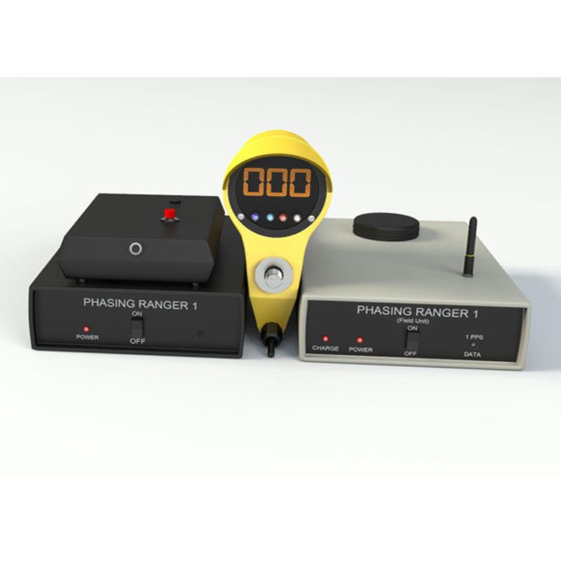
Meter Probe Set-Up & Testing
- The Meter Probe completes a self check each time the selector switch is moved from one position to another. It displays the number 510+/-5 (full scale) and blinks, 0, 120, 240 phase sequence indicator lights followed by a blinking D/Y (Delta/Wye Transformation) indicator light.
- The internal 9V battery voltage should be checked by turning the rotary selector switch to the T position and holding for several seconds until the indicator light stops blinking. If the battery voltage displayed is less than 8 volts, shown on the meter as 080, the battery should be replaced. A standard 9 volt battery is located behind the live line tool attachment.
Send Unit and Receive Unit Set-Up & Testing
- Permanently place satellite receiver (GPS) where there is a clear view of the sky, i.e. window sill (non-tinted), preferably outside on the building structure with a minimum distance of 16 inches from the wall.
- Attach Auto Answer Device to Send Unit labeled “TO AUTO ANSWER DEVICE” via audio cable then attach Auto Answer Device to a land line telephone outlet. If the phone line goes through an internal phone system some system programming may need to be required to make the unit operational.
- Plug in wall adapter into any 115 VAC standard outlet and plug other end into Send Unit labeled “AC IN 15V MAX”. It is very important that this adapter is not removed or rotated form this outlet, this is your Reference Phase information.
- Turn switch to the ON position, both lights (red and white) should blink momentarily and then the red light (Power) should remain on.
- Within several minutes the white light (1PPS Data) should begin blinking rapidly (1 Pulse Per Second) indicating the GPS is working correctly.
- The Send Unit is no ready to receive calls.
- Plug Receive Unit into a 12VDC power outlet or an 115VAC outlet using cables supplied, the “charge” red light should turn On.
- Place unit in a location where there is a clear view of the sky (dashboard of automobile is suitable).
- Turn switch to the ON position, both lights (Red Power and White 1PPS Data) should blink momentarily and then the red light (Power) should remain On.
- Within several minutes the white light (1PPS Data) should begin blinking rapidly (1 blink per second).
- Using a cellular phone, dial the number that is attached to the Auto Answering Device. A tone similar to a fax tone should be heard over the phone line, this is your reference phase data via the Send Unit.
- Once a tone is received, use the supplied audio cable or Blue Tooth to attach the cell phone to the Receive Unit. The white light (1PPS Data) should be solid, indicating data is being received.
- Turn on the Meter Probe and turn the “DEG” position ONLY.
- Make Direct contact with a known phase, i.e. “A, B, or C” phase, “1, 2, or 3” phase.
- For example: If a 120 degree reading is expected while making direct contact but the Meter Probe displays 200 degrees, the following should be performed. With the “Degrees Offset” binary switches (All defaulted UP), switch down the numbers 64 and 16. This will “subtract” 80 degrees out of the original reading and now display 120 degrees. The binary switches ONLY subtract, they do NOT add. Some minor adjustments, such as “2” or “4” may be needed due to any grid fluctuations or Meter positioning, this is normal.
- The “Degree Offset” is a One-time set-up procedure, no other adjustments are ever necessary unless the Send Unit is moved to another location or the reference phase is changed.
- If a “Degree Offset” is necessary in the field, i.e. Transmission to Distribution readings (30 degree offset), working in another utility system (storm damage, new construction), then the binary dip switches can be manipulated anywhere form 0-360 degrees in the same manner as setting the Send Unit.
Phase Angle Measurements
Direct Contact from 120/208V to 69kV including Capacitive Test Points
- Attach the Meter Probe to the appropriate length live line tool for the voltage being testing. Minimum 2 feet.
- Set the selector switch to the Deg position.
- Using the meter probe, contact the energized conductor.
- If the conductor is in phase, the Meter Probe should indicate near zero degrees on the digital display and show a White zero degree indication light.
- If the conductors are out of phase, the Meter Probe will indicate either of the following:
- Nominal 120 degrees and a 120 degrees indicator light or
- Nominal 240 degrees and a 240 degrees indicator light
Delta/Why Transformation
- Expected phase angles when phasing a three-phase system are 0 degrees, 120 degrees, and 240 degrees. The PD800W continuously monitors all phase angles between the Send Unit and the Meter Probe when using the DEG position.
- If the phase angle deviates more than +/- 20 degrees from any of the three expected values of 0, 120, or 240 degrees the Yellow “D/Y” light will blink.
Non-Contact from 69kV to 800kV
- Attach the Meter Probe to appropriate length live line tools for the voltage being tested. Minimum 2 feet.
- Select the DEG position on the Meter Probe.
- Bring the Meter Probe to a distance form each conductor that is close to the minimum approach distance for the voltage being tested to verify all conductors are energized.
- If the conductor is the same phase, the Meter Probe should indicate near zero degrees on the digital display and show a White zero degree indication light.
- If the conductor is out of phase the Meter Probe should indicate either of the following:
- Nominal 120 degrees and a 120 degrees indicator light or
- Nominal 240 degrees and a 240 degrees indicator light
Testing Phase Sequence
- Attach the Meter Probe to the appropriate length live line tools for the voltage being tested.
- Set the selector switch to the Deg position.
- Touch or approach “1” (“A”) phase with the Meter Probe indicated by a near zero degrees and a 0 degree light. Send unit must be attached to know “1” (“A”) phase.
- Touch or approach “2” (“B”) phase with the Meter Probe.
- Sequence (1-2-3)(A-B-C) will be indicated by a nominal 120 degrees on the digital display and a 120 degree indicator light.
- Sequence (3-2-1)(C-B-A) will be indicated by a nominal 240 degrees on the digital display and 240 degree indicator light.
E. Maintenance
- High voltage probe assemblies shall be wiped clean prior to each use with a silicone impregnated cloth and kept clean and free of any contaminants.