
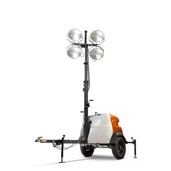
I. Purpose & Scope
To safely and effectively provide instruction on the inspection and proper use of light towers.
II. Definitions
Standard PPE – High Viz Garment, Hard Hat, Z-87.1 Safety Glasses, Gloves, Pants, Work Boots
III. Process
NOTE: Work instruction does not supplement the manual. For specific instructions for the exact model please refer to the owner’s manual.
A. Potential Hazards
- Electrical Shock Hazard
- Fall Hazard
- Rollover Hazard
- Fire and Explosion Hazard
- Burn Hazard
- Entanglement/Sever Hazard
B. PPE
- Standard PPE
C. Inspection
- Check that all safety and operation decals are present and legible.
- Check the following components for wear and damage, and for proper operation:
- Tongue Jack
- Check for rust or damage. Repair or replace as needed.
- Check for proper operation.
- Hitch Assembly
- Check for rust or damage. Repair or replace as needed.
- Check for proper operation.
- Check hardware for proper tightness. Tighten as needed.
- Safety Chains
- Check for rust or damage. Repair or replace as needed.
- Check hardware for proper tightness. Tighten as needed.
- Trailer Lighting Cable
- Check for cut, frayed or bare wires. Repair or replace as needed.
- Check connector for damage. Repair or replace as needed.
- Tires
- Check for wear, cuts, cracks, etc. Replace as needed.
- Check and adjust inflation pressure.
- Axle and Undercarriage
- Check for rust or damage. Repair as needed.
- Outriggers and Stabilizer Jacks
- Check for rust or damage. Repair or replace as needed.
- Check for proper operation.
- Electrical Wiring
- Check for cut, worn or bare electrical wiring. Repair as needed.
- Engine
- Check for leaks or other signs of wear or damage. Repair as needed.
- Check the air cleaner to be sure it is firmly attached, and that the air cleaner seals and hose clamps are properly secured. Check the air cleaner element. Replace if necessary.
- Light Tower
- Check for worn or frayed cables, hydraulic leaks, etc. Repair as needed.
- Check and adjust the hydraulic fluid level.
- Tower Lights
- Check for broken lenses, bulbs, etc. Repair or replace as needed.
- Engine Oil
- Check and adjust fluid levels.
- Engine Coolant
- Check and adjust fluid levels.
- Fuel
- Check and adjust fluid levels.
- Tongue Jack
D. Use
Connect Towing
- Chock the wheels. Position a wheel chock firmly against the front and rear of the wheel on each side of the light tower trailer.
- Use the tongue jack to raise the trailer tongue.
- Position the tow vehicle hitch under the trailer hitch.
- Couple the trailer hitch to the tow vehicle hitch.
- Connect the safety chains.
- Connect the trailer lighting cable.
- Retract the tongue jack.
- Remove the wheel chocks.
Disconnect Towing
- Chock the wheels
- Deploy the tongue jack.
- Disconnect the trailer lighting cable form the tow vehicle lighting cable.
- Remove the safety chains from the safety chain pockets on the tow vehicle.
- Uncouple the trailer hitch from the tow vehicle hitch.
- Move the tow vehicle away from the unit.
Lifting
- Be sure the light tower is fully lowered and locked in the transport position.
- Use forklift blades at least 60 inches long when lifting the unit. Insert the forklift blades fully into the forklift pockets.
- Use only shackles or a locking type hook when using the lifting eye.
- On manual tower models, the lifting eye and upper forklift pockets are incorporated into the light tower assembly. Be sure the light tower is lowered and locked in the transport position before lifting the unit.
- Secure the unit at the tie-down points with appropriately rated chains or straps.
- Do not apply more than 600lbs force on the chains or straps.
- The truck operator is responsible for securing the load properly to the transport trailer.
Operation
- Set up on smooth, flat, solid ground surfaces only.
- Do not set up on inclines of more than 2.8 degrees front-to-back and side-to-side.
- Consider the height of the light tower when fully raised. Avoid areas with trees and power lines and other overhead obstructions.
- Do not operate in winds exceeding 53mph.
- Position the unit at the work site.
- Chock the wheel.
- If the unit was, disconnect from the tow vehicle.
- Level the trailer using the tongue jack.
- Deploy the outriggers and stabilizer jacks.
- Adjust the tower lights.
- Raise the light tower.
Deploying Outriggers and Stabilizer Jacks
- Raise the outrigger locking pin.
- Fully extend the outrigger until the locking pin engages the outrigger operation position.
- Remove the stabilizer jack locking pin.
- Rotate the stabilizer jack 90 degrees into the operating position, and install the stabilizer jack locking pin. Ensure the pin is inserted fully through the stabilizer jack.
- Unfold the jack handle to the operating position.
- Turn the jack handle clockwise until the jack foot is firmly planted on the work site surface.
- Repeat for the remaining outriggers and stabilizer jacks.
- Once all outriggers and stabilizer jacks are deployed, use the stabilizer jacks and tongue jack to help level the unit on the work site ground.
Retract Stabilizer Jacks
- Turn the jack handle counterclockwise to fully raise the jack foot.
- Fold the jack handle to the transport position.
- Remove the stabilizer jack locking pin.
- Rotate the jack 90 degrees to the transport position, and install the stabilizer jack locking pin. Make sure the pin is inserted fully through the stabilizer jack.
- Raise the outrigger locking pin.
- Retract the outrigger into the transport position. Be sure the locking pin engages.
- Repeat for the remaining outriggers and stabilizer jacks.
Adjusting Tower Lights
Hydraulic Towers LED
- Set the light bar to the preferred work angle.
- Pull the park pin and rotate 90 degrees to unlock the light bar.
- Rotate the light bar to the preferred work angle.
- If the light bar rotates loosely or does not remain in the preferred work position.
- Remove the cap plug from the center of the light bar.
- Tighten the pivot nut until desired resistance is achieved.
- Replace the cap plug.
- Set the tower arms to the preferred work angle.
- Loosen the adjustment nut on each tower arm.
- Pull the park pin and rotate 90 degrees to unlock the tower arm.
- Rotate each tower arm to the preferred work angle.
- Tighten the adjustment nuts.
- Set each individual light fixture to the preferred work angle.
- Yoke center pivot adjusts the horizontal angle of each individual light fixture. Grasp the side of the yoke to adjust.
- Fixture pivots adjust the vertical angle of each individual light fixture. Loosen the locking clasp, move the light fixture up or down to adjust, then tighten the locking clasp.
Hydraulic Towers Metal Halide
- Set the light bar to the preferred work angle.
- Pull the park pin and rotate 90 degrees to unlock the light bar.
- Rotate the light bar to the preferred work angle.
- If the light bar rotates loosely or does not remain in the preferred work position.
- Remove the cap plug from the center of the light bar.
- Tighten the pivot nut until desired resistance is achieved.
- Replace the cap plug.
- Set the tower arms to the preferred work angle.
- Loosen the adjustment nut on each tower arm.
- Pull the park pin and rotate 90 degrees to unlock the tower arm.
- Rotate each tower arm to the preferred work angle.
- Tighten the adjustment nuts.
- Set each individual light fixture to the preferred work angle.
- Yoke center pivot adjust the horizontal angle of each individual light fixture. Grasp the sides of the yoke to adjust.
- Fixture pivots adjust the vertical angle of each individual light fixture. Move the light fixture up or down to adjust.
Manual Tower LED
- Set each individual light fixture to the preferred work angle.
- Yoke center pivot adjusts the horizontal angle of each individual light fixture. Grasp the sides of the yoke to adjust.
- Fixture pivots adjust the vertical angle of each individual light fixture. Loosen the locking clasp move the light fixture up or down to adjust, then tighten the locking clasp.
- The light tower can also be rotated to provide additional adjustment of the light angle.
Manual Tower Metal Halide
- Set each individual light fixture to the preferred work angle.
- Yoke center pivot adjusts the horizontal angle of each individual light fixture. Grasp the sides of the yoke to adjust.
- Fixture pivots adjust the vertical angle of each individual light fixture. Move the light fixture up or down to adjust.
- The light tower can also be rotated to provide additional adjustment of the light angle.
Raising and Lowering the Light Tower
Hydraulic Towers
- To raise the light tower move the tower switch on the control panel to the UP position to raise the tower to the preferred height.
- To lower the light tower turn the tower lights off before lowering the light tower.
- Move the tower switch on the control panel to the DOWN position until the tower is fully lowered.
- Hold the tower switch in the DOWN position for three additional seconds, to make sure the tower is fully lowered.
Manual Towers
- To raise the light tower, unlatch the tower locking pin.
- Turn the winch handle clockwise until the light tower is vertical.
- Lock the light tower in the operating position with the latch pin.
- To rotate the light tower to the preferred work angle, loosen the tower lock knob.
- Use the handles to rotate the light tower to the preferred work angle.
- Tighten the tower lock knob.
- To lower the light tower, turn the tower lights off before lowering the light tower.
- Rotate the light tower to the transport position.
- Loosen the tower lock knob.
- Use the handle to rotate the tower to the transport position.
- Tighten the tower lock knob.
- Turn the winch handle on the light tower counterclockwise until the telescoping masts are fully lowered.
- Turn the winch handle on the right side of the unit clockwise to make sure the lower light tower cable is taut.
- Unlock the latch pin at the foot of the light tower.
Fueling
- Open the engine compartment access door to access the fuel tank.
- Open the filler cap.
- Add fuel as needed.
Operating the Engine
- Turn the ignition switch on the control panel counterclockwise to PREHEAT. Hold for approximately 20 seconds.
- Turn the switch clockwise past RUN to START.
- Once the engine starts, release the switch; it will return to the RUN position.
- To shut down the engine with the standard ignition switch, turn the ignition switch counterclockwise to the OFF position.
Operating Tower Lights
- To turn the lights on: The tower lights are automatically controlled by the Sequenced Lighting System. Leave the light breaker switches, located on the light control panel, in the ON position for automatic light control. However, individual lights can be manually controlled by the light breaker switches.
- To turn the lights off: Shutting the engine down will automatically turn off the lights. However, individual lights can be manually turned off by turning one or more of the light breaker switches to the OFF position.
Shutting Down the Unit
- Shut down the tower lights.
- Shut down the engine.
- Lower the light tower.
- Adjust the lights to the transport position.
- Retract the stabilizer jacks and outriggers.
E. Maintenance
- Use NGLI consistency #2 high-temperature anti-friction bearing lubricating grease for all trailer mechanical pivot points.
- Clean the light tower trailer to remove all dust, dirt or other foreign material.
- Clean the light tower and light fixture assemblies with a damp cloth or sponge.
- Clean all electrical wiring and components by hand using non-corrosive cleaner.
- Clean the inside of the engine compartment.
- Clean any oils or spills inside the engine compartment.
- Empty the fluid containment tray (if equipped).