
I. Purpose & Scope
To safely and effectively provide instruction on the inspection and proper use of circular saws.
II. Definitions
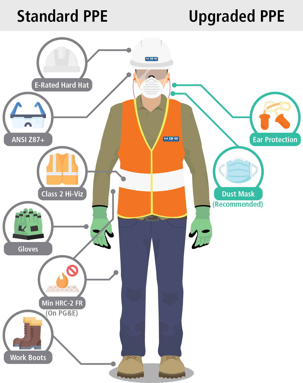
Standard PPE – High Viz Garment, Hard Hat, Z-87.1 Safety Glasses, Gloves, Pants, Work Boots
III. Process
NOTE: Work instruction does not supplement the manual. For specific instructions for the exact model please refer to the owner’s manual.
A. Potential Hazards
- Flame/Fire Hazards
- Electric Shock Hazard
- Cutting Hazard
- Kickback Hazard
- Flying Debris
B. PPE
- Standard PPE
- Hearing Protection
- Respiratory protection – Recommended
C. Inspection
- Inspect blades for cracked, broken teeth or dullness. Replace blades as necessary.
- Check the operation and condition of the lower guard lever. If the guard and lever are not operating properly, they must be serviced before use. Lower guard may operate sluggishly due to damaged parts, gummy deposits, or a buildup of debris. Check lower guard by following the below procedure.
- Remove battery pack before checking the lower guard.
- Place the tool on its side.
NOTE: This procedure will not show proper lower guard operation if the tool is not on its side. - Grasp the lower guard by the sides and push it all the way back into the blade housing.
- Release the lower guard.
- If the guard immediately springs back into place, it is working correctly and you may continue with use.
- If the guard does not immediately spring back into place, clean the upper and lower guards to remove all chips and debris. Then check the operation again.
- Inspect tool for undue noise, misalignment or binding of moving parts, breakage of parts, or any other condition that may affect the tool operation.
- Inspect the saw regularly to make sure the blade is 90 degrees to the shoe. To inspect and adjust the blade back to position follow the below procedure.
- Remove battery pack.
- Set the bevel pointer to zero.
- To make sure the blade is 90 degrees to the shoe, place saw on the blade side and retract lower guard. Place a square against the blade and shoe to inspect the degree setting.
- To adjust the degree setting, loosen the bevel adjusting knob. Turn the bevel adjustment screw in or out until the blade is at a 90 degree angle with the shoe.
- Tighten the bevel adjusting knob securely.
D. Use
Installing and Removing Blades
- Remove battery pack before installing or removing blades.
- Place the saw on a flat surface with the blade facing upwards. To remove the bolt from the spindle, push in the spindle lock button. While holding in the spindle lock button, use the wrench provided with the tool to turn the bolt counterclockwise. Remove the bolt and blade flange.
- Slide the lower guard lever up to raise the lower guard. Remove the blade form the spindle. Always clean the spindle, upper guard and lower guard to remove any dirt and dust.
NOTE: Do not remove inner blade flange. Larger diameter of inner flange should face the blade. - To install a blade, place the blade on the spindle with the teeth pointing in the same direction as the arrow on the lower guard. Release the lower guard lever.
- Place the blade flange on the spindle and hand tighten the bolt.
- While holding in the spindle lock button, use the wrench to turn the bolt clockwise and tighten.
Adjusting Depth
- Remove battery pack.
- To adjust the depth of the cut, hold the saw by the handle and loosen the depth adjusting level by pushing it down toward the shoe.
- Raise or lower the shoe to the desired position. Markings in 1/4″ increments are located on the inner side of the upper guard for depth setting. For the proper depth setting, the blade should extend no more than 1/8″ to 1/4″ below the material being cut. (When cutting masonry, use a diamond blade. Make successive passes at depths of less than 1/4″ to achieve the desired depth. Cutting a depth of more than 1/4″ will damage the wheel).
- Lift the depth adjusting level up toward the motor housing to secure the shoe position.
Adjusting Bevel Angle
- Remove battery pack.
- To adjust the angle of the cut, hold the saw by the handle and loosen the bevel adjusting knob.
- Hold the front of the shoe and rotate the saw by the handle to the desired angle as indicated by the markings on the bevel scale.
- Tighten the bevel adjusting knob securely.
General Operation
- Draw a cutting line.
- Place the front of the shoe on the edge of the workpiece without making blade contact.
- Hold the handle with one hand and the other front handle with the other.
- Line up the sight line with your cutting line. Position your arms and body to resist kickback.
- To start the saw, push the lock-off button down while pulling the trigger. Allow the motor to reach full speed before beginning cut.
- While cutting, keep the shoe flat against the workpiece and maintain a firm grip. Do not force the saw through the workpiece. Forcing a saw can cause kickback.
- If making a partial cut, restarting in mid-cut or correcting direction, allow the blade to come to a complete stop.
- To resume cutting, center the blade in the kerf, back the saw away from the cutting edge a few inches, push the lock-off button down while pulling the trigger and re-enter cut slowly.
- If the saw binds and stalls, maintain a firm grip and release the trigger immediately. Hold the saw motionless in the workpiece until the blade comes to a complete stop.
- After finishing a cut, be sure the lower guard closes and the blade comes to a complete stop before setting the saw down.
E. Maintenance
- When cutting masonry and metal, remove battery pack and frequently clean dust from air vents and guards.
- Clean dust and debris from vents.
- Keep handles clean, dry and free of oil or grease. Use only mild soap and a damp cloth to clean.
- If water pressure is sufficient but water is not coming out to the blade, unlock the nut over the blade cover and utilize wire to break out sediment.
(Performed by Authorized Personnel Only)
Manufacturer: Milwaukee
Model: M18
| Potential Energy Hazards | Method of Neutralizing Energy | Permits Required |
|---|---|---|
 Electric Electric Air Air | LOTO Disconnect lines | Safe work |
| Pneumatic Gravity | Block/bleed Release pressure | Hot work |
| Mechanical Gas | Set fire watch Confined space permit | Line blanking |
| Hydraulic Water | Confined space |
Lockout (Shut-Down Procedure)
- Notify all affected personnel.
- Turn off unit.
- Remove battery pack.
- Tagout the battery pack.
Start-up Procedure
- Notify all affected personnel that equipment is operational and removal of tagout will occur.
- Remove all tools, equipment and debris from the area.
- Remove tagout from the battery pack.
- Reconnect the battery pack to the tool and test equipment.