
I. Purpose & Scope
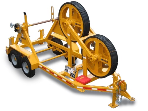
To safely and effectively provide instruction on the inspection and proper use of bullwheels.
II. Definitions
Standard PPE – High Viz Garment, Hard Hat, Z-87.1 Safety Glasses, Gloves, Pants, Work Boots
III. Process
NOTE: Work instruction does not supplement the manual. For specific instructions for the exact model please refer to the owner’s manual.
A. Potential Hazards
- Moving Parts Hazard
- Hydraulic Pressure Hazard
- Burn Hazard
- Fire hazard
B. PPE
- Standard PPE
C. Inspection
- Inspect the machine daily for potential fire hazards and make any necessary repairs immediately.
- Inspect for loose threaded connections.
- Inspect for metal fatigue or excessive corrosion.
- Inspect for abraded hose surfaces.
- Inspect for hydraulic fluid leakage.
- Inspect for any possible obstruction of moving parts – especially in the drive train.
D. Use
Brake Control
- The hydraulic brake calipers for the bullwheels are controlled with a single pressure control. The pressure control is equipped with a pressure gauge to aid in monitoring unit performance.
Field Set Up
- Locate the unit on as level ground as possible, lined up with the towers at a minimum distance of 300 feet from the foot of the first tower or 3 times the height of the first tower, whichever is greatest.
- Anchor the unit in the opposition to the direction of the pulling force with anchors that will hold three times the maximum rating of the machine.
- To protect against electrical hazards due to induction or electrical contact, the system must be connected to a proper ground rod or the electrical system neutral using the grounding bars provided on the unit. Follow proper grounding procedures as required by IEEE and/or the applicable standards in your area. Use of a ground mat and a running ground on the conductor are highly recommended.
- Put a hazard barrier around the perimeter of the unit to keep unauthorized personnel away from the equipment.
Threading the Bullwheels
- Release the bullwheel brakes by turning the bullwheel pressure control counter-clockwise.
- Thread the bullwheels with a length of rope by starting with lower bullwheel and wrapping it around the top bullwheel while moving from right to left.
- Connect the rope to the pulling line.
- Pull the rope to rotate the bullwheels until the pulling line is threaded around the bullwheels.
- Connect the pulling line to the conductor.
- Apply the brakes by turning the bullwheel pressure control clockwise.
Tensioning
- Adjust the reelshaft brake to provide tail tension from the reel to the bullwheels.
- Turn the bullwheel tension control fully clockwise to hold the tensioner bullwheels stationary.
- When the pulling machine starts, turn the tension control counter-clockwise slowly until the bullwheels start to turn.
- Re-adjust the reelshaft brake control to adjust the tail tension from the reel to the bullwheels.
- Adjust tension control as required during pulling operation in order to maintain the desired tension in the conductor.
- To stop the pull, the pulling unit must stop first. Do not attempt to stop the pull using the tensioner.
Removing the Reel
- Turn the reel until the drive arm and lifting loop are in vertical (up) position.
- On the drive arm side, pull the ball lock pin straight up, and pull the reel shaft pin back enough to allow the reel shaft to be lifted up.
- Attach lifting hooks to the drive arm and lifting loop. Ensure they are balanced so the reel remains level during lifting.
- Lift the reel straight up.
- Remove the bronze bearing form reel shaft.
- Loosen the nuts on the lifting loop and remove it from reel shaft.
- Remove reel shaft from reel.
Loading a Reel
- Turn the reel drive until the shaft coupling drive teeth face up.
- On the drive arm side, pull ball lock pin straight up and pull the reel shaft pin back enough to allow the reel shaft to be installed.
- On the lifting loop side, open the locking latch and swing it back out of the way.
- Put the reel shaft in the reel, making sure the conductor or rope will wind on or off from the top of the reel in the correct direction.
- Make sure the reel shaft drive pins are fully engaged in reel drive holes.
- Install the lifting loop tight against side of the reel to hold it firmly against the drive arm and keep it from sliding sideways. Torque nuts on locking collar to 200ft-lbs.
- Install the bronze bearing on end of the reel shaft.
- Attach lifting hooks to the drive arm and lifting loop, making sure they are balanced so the reel remains level during lifting.
- Lower the reel in place engaging the reel shaft drive with its mating part and make sure the bronze bearing locates in the bearing support.
- Push the reel shaft pin back into place and insert the ball lock pin to hold the reel shaft pin in place.
- Swing the locking latch back into place over the bronze bearing and insert the safety pin.
E. Maintenance
- Always ensure that excess grease and oil accumulation, including spillage, are cleaned up immediately.
- Use only nonflammable cleaning agents for cleaning the machine or any machine component.
- Lubricate reelshaft bushings daily.
- Inspect and correct bolted connections, hydraulic plumbing, and hydraulic reservoir.