
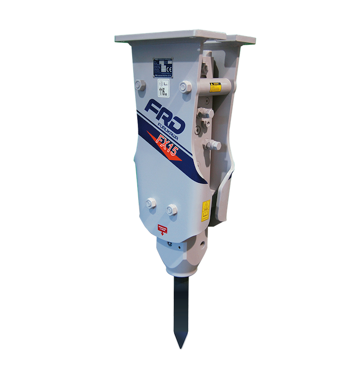
I. Purpose & Scope
To safely and effectively provide instruction on the inspection and proper use of breaker attachments.
II. Definitions
Standard PPE – High Viz Garment, Hard Hat, Z-87.1 Safety Glasses, Gloves, Pants, Work Boots
III. Process
NOTE: Work instruction does not supplement the manual. For specific instructions for the exact model please refer to the owner’s manual.
A. Potential Hazards
- Falling Objects Hazard
- Flying Debris Hazard
- Fire Hazard
- Electrical Shock Hazard
- Swing Radius Hazard
- Rollover/Tipping Hazard
- Burn Hazard
- Hazardous Atmosphere
- High Pressure Oils Hazard
- Hydraulic Pressure Hazard
- Explosive Pressure Hazard
B. PPE
- Standard PPE
C. Inspection
- Clean the hydraulic breaker before inspection.
- Check for oil leakage.
- Check for missing, damaged or looseness of components.
- Check for crack, damage or looseness of the rod.
- Check gas pressure in the gas tank located at the upper part of the hydraulic breaker.
D. Use
- When attaching/detaching the oil hose plug and union cap, clean them well to prevent entry of dust.
Mounting on Base Machine
- Place the hydraulic breaker on timber. (Attach hoses and bushings.)
- Move the base machine to align the hydraulic breaker with the arm. Lower the boom and align the pin hole at the end of the arm with the pin hole in the bracket.
- Insert a pin, install a stop ring, and attach a bolt.
NOTE: When positioning pin holes, do not put your hand or fingers in them, otherwise your hand or finger may be cut off when the arm or hydraulic breaker moves. - When the arm pin is inserted, raise the boom, and place the breaker on the timber. Extend the bucket cylinder, and insert the pin into the hole in the bucket link.
- Install the stop ring, and install the retaining bolt. Bolt locking is of a double-nut type. Tighten the nuts firmly.
- Stop the engine at the base machine, turn off the main switch, and let out the air from the hydraulic oil tank.
- Check that the stop valves on both sides of the end of the arm are in the “Close” position.
- Remove the union cap and oil hose plug from the hydraulic breaker pipe attached to the end of the arm, and connect the oil hose.
NOTE: Provide a pan to collect waste oil before attaching/detaching the oil hose. Wipe the spilt oil completely. Exercise sufficient care so that dust will not enter through the metal fittings at the end of the oil hose. - Start the engine of the base machine, and raise the boom. Then operate the bucket cylinder to straighten the twisted connection hose of the hydraulic breaker.
- Turn the high-/low-pressure stop valve on the hydraulic breaker pipe at the end of the arm by 90 degrees (the line on the head shows the direction of flow), and connect the hydraulic circuit. (Set the stop valve in the fully open position).
NOTE: The rod may shoot out by the hydraulic pressure in the piping, do not stand near the rod.
Removal of Hydraulic Breaker
- Place the hydraulic breaker on a flat place.
- Stop the engine of the base machine, and let the air pressure out of the hydraulic oil tank.
- Fully close the stop valve at the end of the arm.
- Mount the union cap and oil hose plug on the oil hose and the end of the arm.
- Place the removed pins and retaining bolts/nuts on the hydraulic breaker side.
Traveling/Stopping
- To secure the forward field of vision and ensure traveling safety, raise the hydraulic breaker 30-40 cm or more form the ground and select flat ground for traveling.
- When traveling an up or down slope, lower the engine speed in advance, and keep the angle between the boom and arm at 90-110 degrees. Keep the hydraulic breaker 30-40 cm above the ground, and travel the machine facing the slop at all times.
- Select a frim ground to park the vehicle. Set the breaker perpendicularly and put the rod end on the ground.
- When leaving the driver’s seat, set the “Safety lock” to prevent the boom and arm from moving, and then stop the engine.
Breaking Operation
- Move the base machine to the front of the concrete to be broken.
- Operate the boom, arm, and bucket cylinder of the base machine, set the breaker perpendicularly to the concrete surface to break, and then push and thrust the breaker against the concrete.
- Step on the breaker pedal to operate the breaker.
- After breaking concreate, return the pedal to the original position immediately.
Precautions
- Stop operation when hoses are vibrating abnormally.
- Stop operation right after breaking. (Avoid idle blows as much as possible)
- Do not move rock.
- Do not wrench open rock.
- Do not hammer continuously for more than one minute. If rock cannot be broken after hammer the same position for one minute, change the hammering position.
- Break large rock from edges.
- Select an appropriate engine speed (rpm) for breaking with the breaker. Run the engine at the specified speed for breaking. The hammering force will not change even if the engine speed is increased. Increased engine speed will cause oil temperature to rise, leading to overheating.
- Do not break rock in water or mud.
- Do not allow the breaker to fall to break rock.
- Do not do breaking operation at the stroke end of the base machine cylinder.
E. Maintenance
- After operation inspect the bolts, check for oil leakage, cracks, damage, wear and hoses.
- Wipe away mud or oil from the floor, pedal and lever.
- Remove mud from the breaker body.